Tutorial: Wi-Fi on 3D printer using ESP3D
One year after the assemble of my 3D printer (esta), I decided to upgrade it by adding a WiFi module. I couldn’t find any complete material about it, so I’m writing it here for anyone who want to do that.
This tutorial is based on my 3D printer, that uses Marlin as its firmware and an Arduino Mega with a RAMPS 1.4 shield. However, it can be useful for printers that use another hardware or firmware, since the firmware is compatible with G-Code and the hardware has UART pins TX and RX that are used as input and output of G-Code to the firmware of the printer.
It will not be necessary to modify the 3D printer firmware. This way, it is his tutorial may also be useful for 3D printers with proprietary firmware and software.
Materials
Hardware
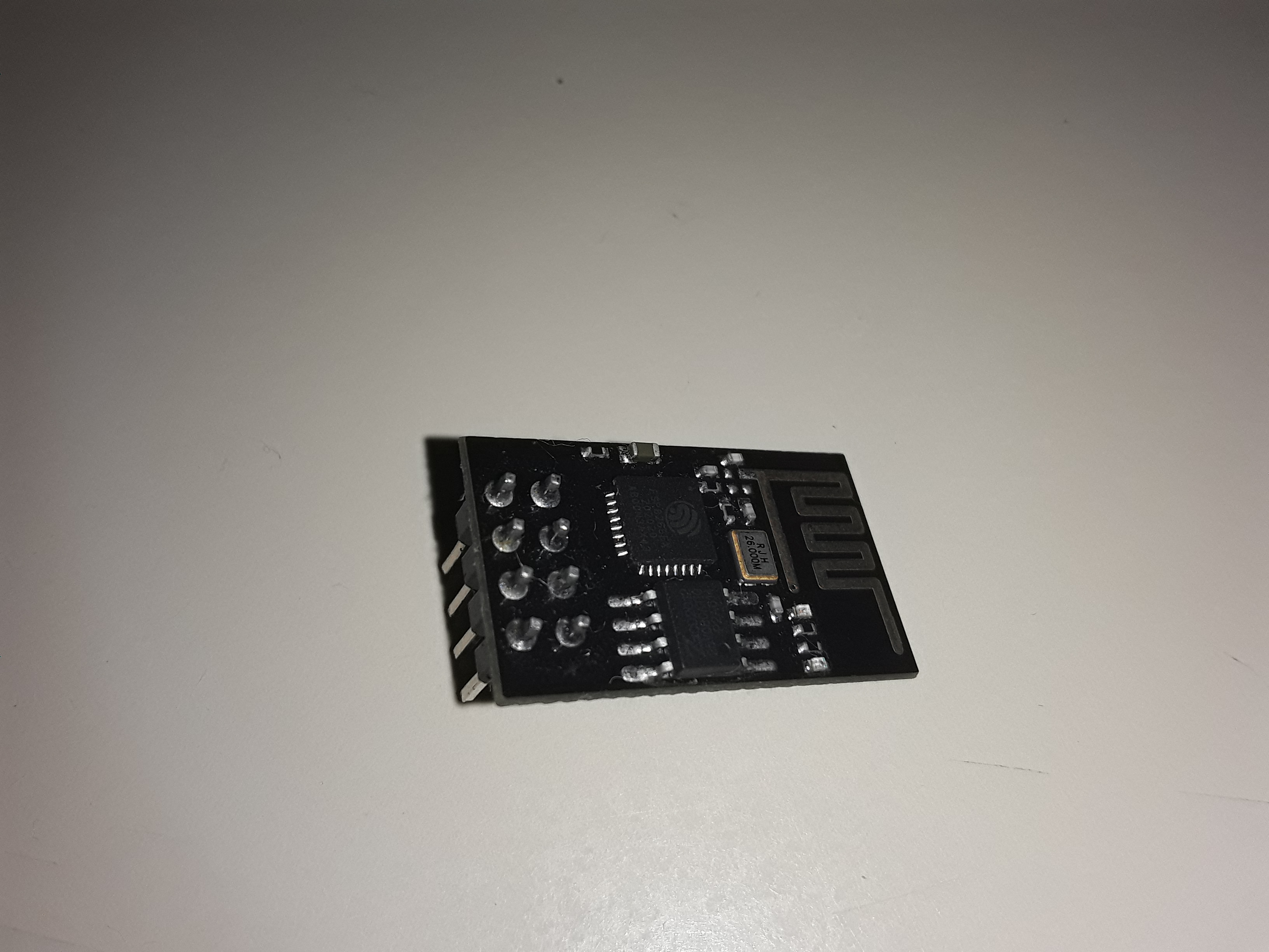
At first, we’ll need a WiFi module ESP-01, that contains an ESP8266 microcontroller, and that is very cheap.
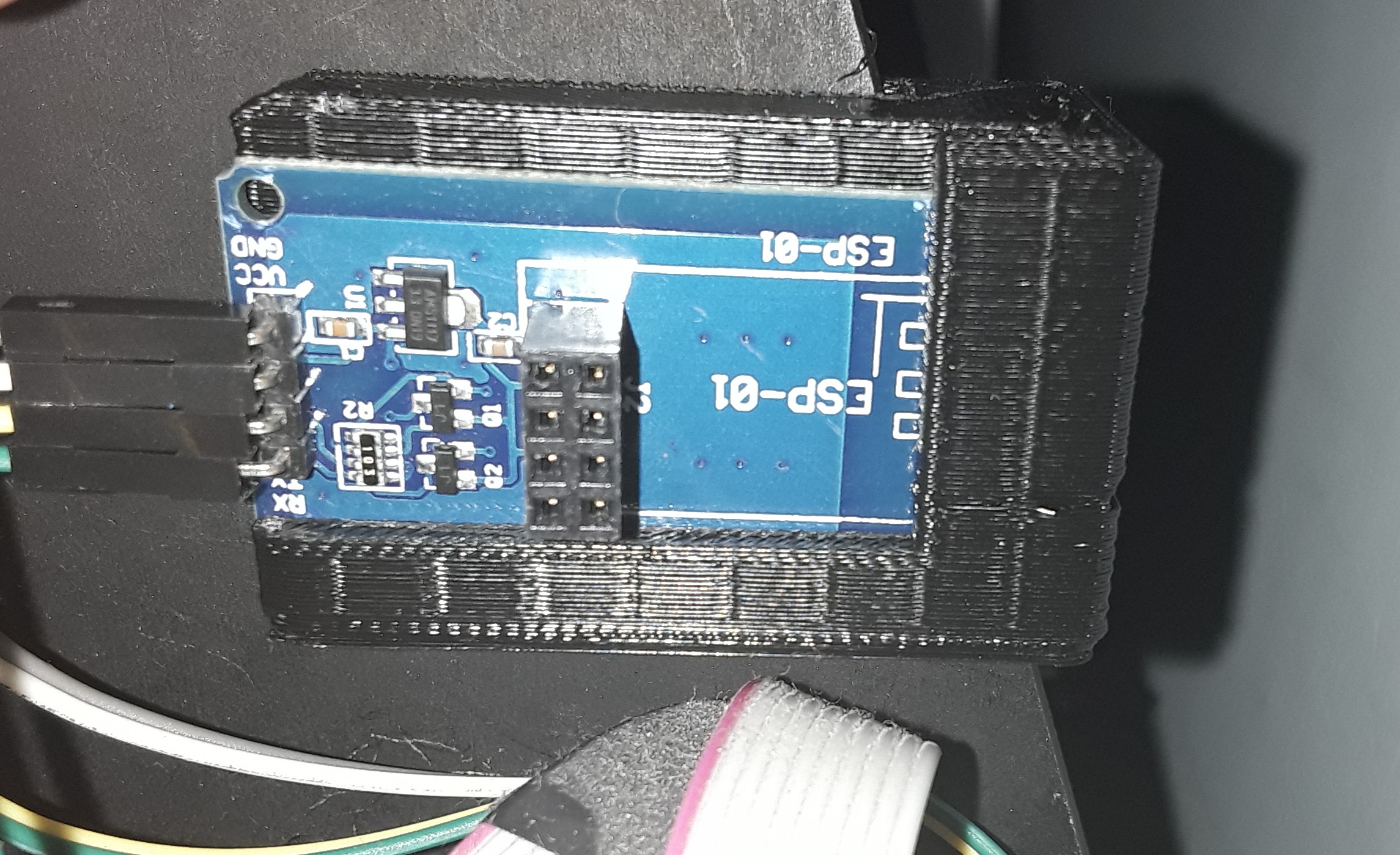
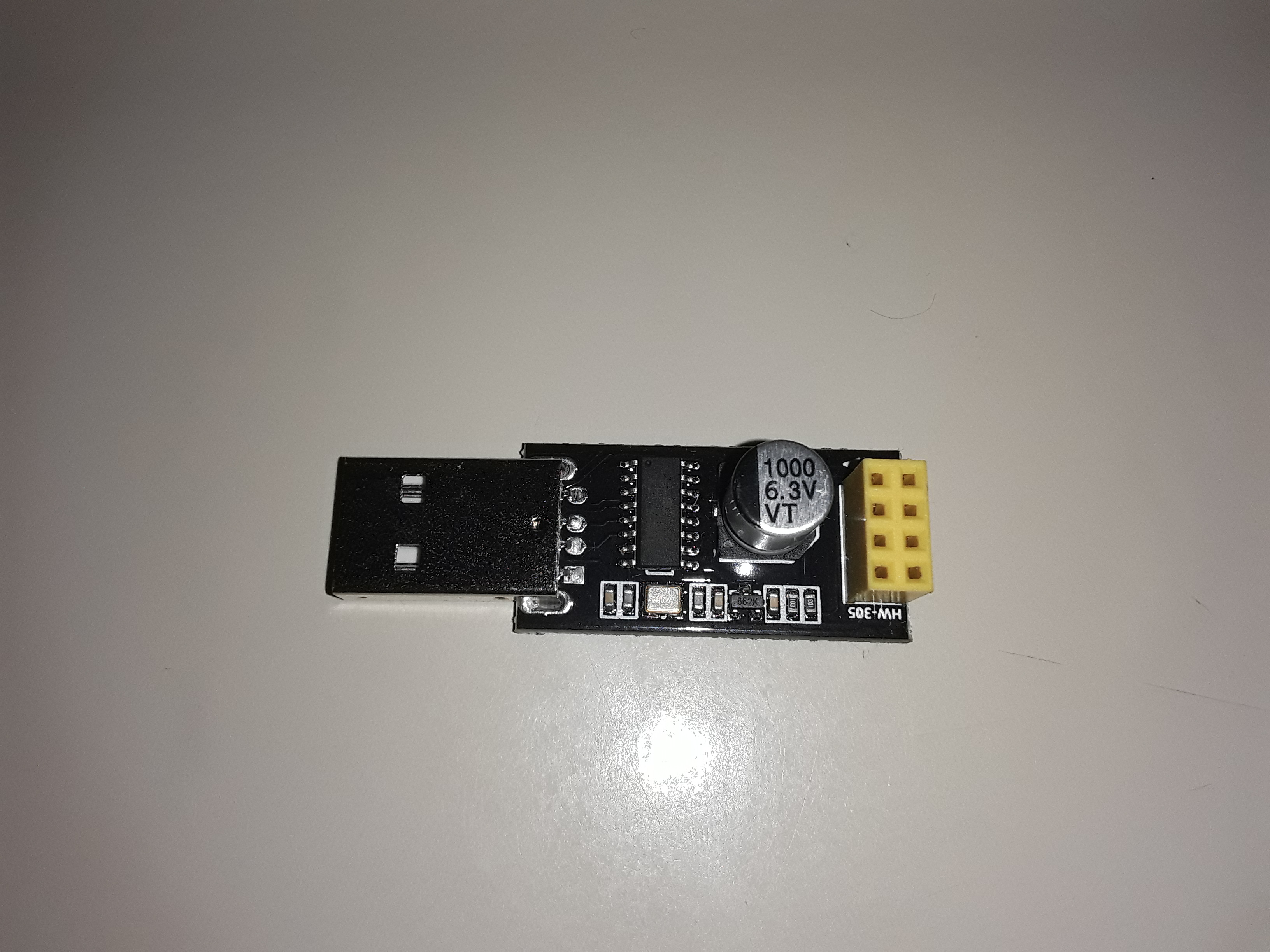
I also add to the list two items that are not obligatory, but I recommend: an ESP-01 adapter for using with Arduino and an ESP-01 to USB adapter.
Software
We’ll install in ESP-01 the firmwware ESP3D (https://github.com/luc-github/ESP3D). To do that, we’ll need to have installed Git, Arduino IDE, and some libraries that I’ll tell you later.
In this tutorial I’m using Manjaro Linux. I believe that in other Linux distros and MacOS this should not be so different from what I’m showing here. On Windows, these steps probabily should be the same, but executed in a different way. Contact me if it’s your case!
ESP3D is a firmware that allows the printer to connect to a WiFi network. It opens two TCP ports: one that listen to G-Code commands and send them to Arduino through UART, and a HTTP port (80) that serves a web page where we can control the 3D printer through a graphical interface.
Getting ESP3D
We can clone ESP3D directly from GitHub. Here I’m using the version 2.1 of ESP3D, and the version 2.0 of the web interface. If you want to change the version, the steps are the same, but using the corresponding branch of each version. I’m using ESP3D-WEBUI version 2.0 because it is smaller and it its on the ESP-01 that I’m using on my printer.
git clone --recursive https://github.com/luc-github/ESP3D.git
cd ESP3D
git checkout 2.1
git submodule update --init
git -C ESP3D-WEBUI checkout 2.0
Arduino IDE setup and installing the libraries
Let’s open ESP3D on Arduino IDE. From the root directory ESP3D that we have cloned, run:
arduino esp3d
Installing the ESP8266 board
If you don’t have the ESP8266 board installed, let’s install it on the board manager of Arduino IDE. In File > Tools, add the following URL in the additional URLs for board managers: http://arduino.esp8266.com/stable/package_esp8266com_index.json.
On Tools > Board > Board Mannager, insall esp8266 on the version 2.7.4.
Installing libraries
The corresponding libraries are in the ESP3D repository. Now we need to copy
them to the Arduino library directory (in my Manjaro, that directory is
~/Arduino/libraries ).
cp -r libraries/* ~/Arduino/libraries/
Flashing ESP3D on ESP-01
On Arduino IDE, in Tools > Boards, select “Generic ESP8266 Module”. In the Tools menu, configure the boards accordingly to the size of the flash memory of your ESP-01 (check this ESP3D reference) to have the best flash memory usage.
In order to burn the firmware on ESP-01, you should connect it to an USB port. You can do that using the USB adapter that I mentioned before. If you don’t have one (or if don’t want to buy one), you can do that using an Arduino to make the USB-UART bridge.
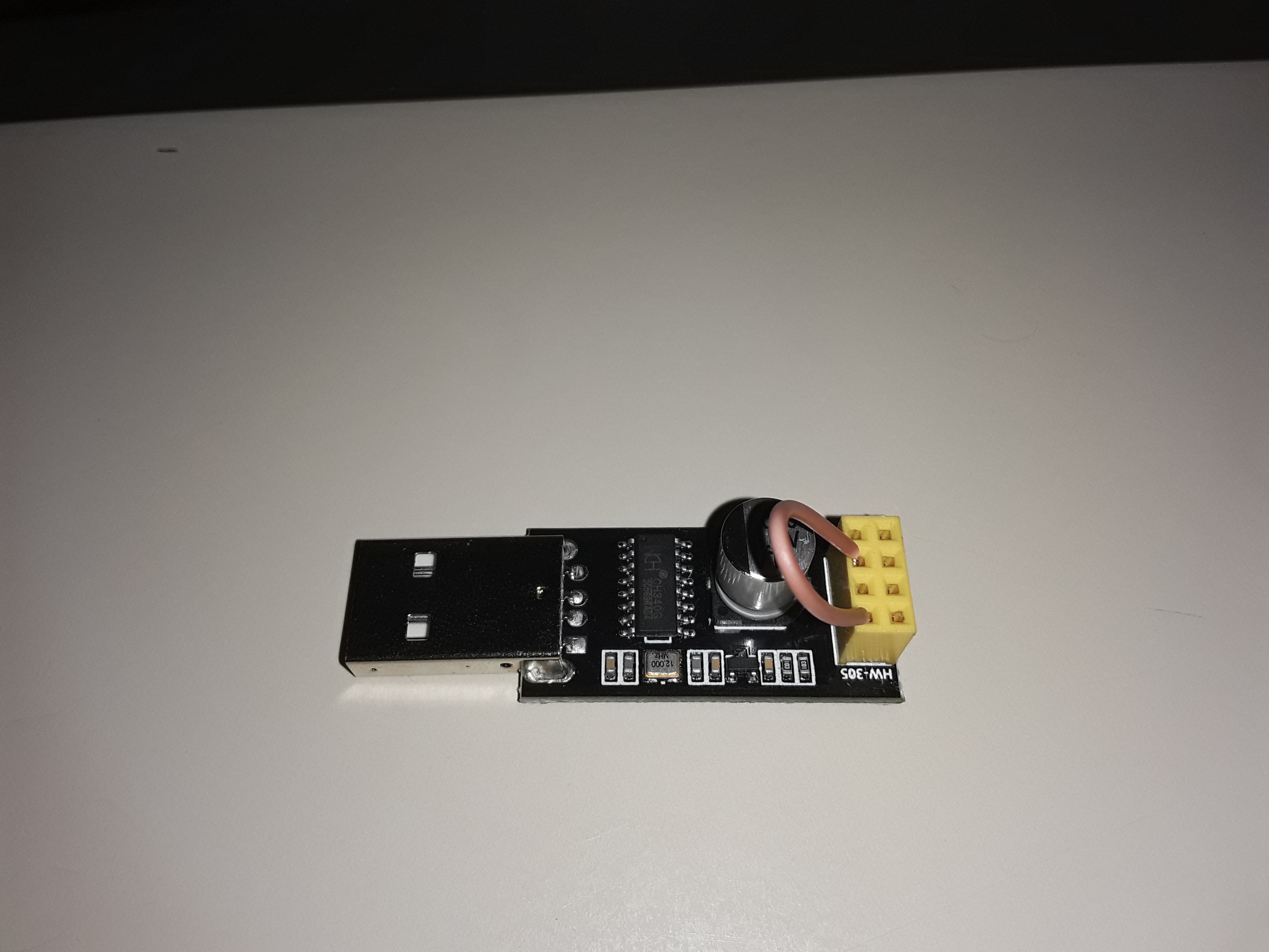
We should connect the GPIO-0 pin to the GND to flash a firmware on ESP-01. If you are using the USB adapter, you can do that using a small jumper wire connecting the two terminals show in the following picture, and connecting the ESP-01 over it:
Para gravar um firmware no ESP-01, devemos ligar o pino GPIO-0 ao GND. Com o
After that, connect it to a USB port on your computer, select the correct port on Tools > Port, and click the upload button.
After the upload, unplug the USB adapter, remove the wire that we placed before, plug again the ESP-01, and connect it to a USB port.
Wait a little, then you’ll find a new WiFi access network called ESP3D. Connect on it (the password is 12345678).
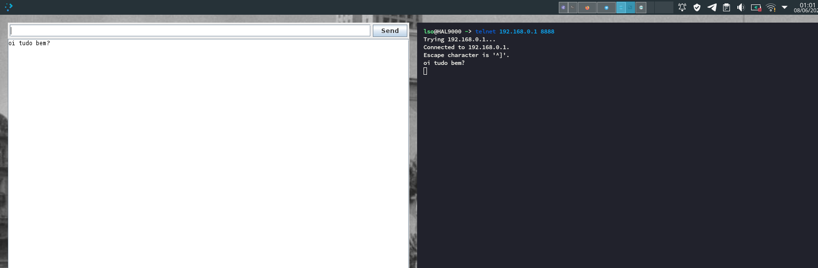
We can test if the serial communication is working. Open the serial monitor on Arduino IDE, using 115200 as baudrate, and on the terminal run:
telnet 192.168.0.1 8888
If everything is OK, everything that you type on one window should also be seen in the other one, like that:
ESP-01 setup
On you browser, go to 192.168.0.1. In this screen you can upload the file with
the ESP3D web interface. Upload the file ESP3D/ESP3D-WEBUI/index.html.gz.
Click on “Go to ESP3D Interface”. After this, the ESP3D configuration wizard will show up. Choose the language, then select you printer firmaware (if don’t known, set Unknown) and the serial baudrate.
In the WiFi settings, you can choose between the Station mode and the Access Point mode. If you choose Access Point, ESP3D will create a WiFi network the same way that we are using until here; if you choose Station, it will connect to an existing WiFi network, using the Access Point as a fallback if it can’t connect. After that, the default interface will show up. In the tab ESP3D there are more WiFi settings, e. g. port numbering, static IP address, etc.
Sugestion: use a static IP address: You can do that by using an IP address that is in the range of your subnet, but outside the DHCP range, or you can add to the DHCP of you WiFi router a rule to provide the same IP address to the MAC address of your ESP-01!
After finishing the wizard, turn off you ESP-01 and turn it on again. Wait a
while (one minute should be enough), connect to you WiFi network and do the same
test that we did before, but now passing the ESP-01 IP address to the telnet
command.
Plugging ESP-01 on the RAMPS shield
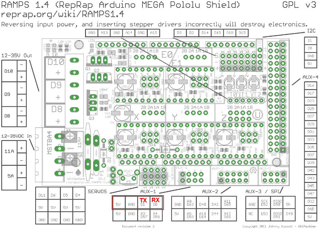
In the RAMPS shield, locate the AUX-1 pins. We’re going to use D0 (RX), D1 (TX), 5V and GND. In the following picture we have a diagram of the RAMPS 1.4 pins, where AUX-1 is placed on the bottom:
If you are using an ESP01 adaptor, you should connect the Vcc pin and the GND pin to the 5V and GND of AUX-1 and the communcation pinx RX and TX of ESP-01 to the TX and RX of AUX-1, respectively (yes, the TX of one in the RX of the other).
If you don’t have that adapter, you can plug the ESP-01 directly. Important: note that ESP-01 works with 3.3V, so you need to plug it on a 3.3V pin or build a circuit to lower to that voltage!
After turn on the printer, ESP-01 should connect to your network, and after that it will be possible to use it. Important: if you want to use your printer through USB, unplug ESP-01!