3D Printer
Introduction
Well, if you came here in this page, you already know what a 3d printer is. So, I’m not going to present too much about this. Let’s go to what matters!
In this project, that I did on my vacations, I built this FDM 3D printer. It has the following features:
- Hot bed;
- G-code compatible;
- Open source and hardware;
- Bowden;
- Auto levelling;
- Graphical display;
- Interface in Portuguese;
- SD card;
- Games
This printer is a copy inspired by the 3d printer
Cianofícea, built by the
member of Hardware Livre USP Bruno.
This post is also available in Portuguese on Hardware Livre website.
Structure
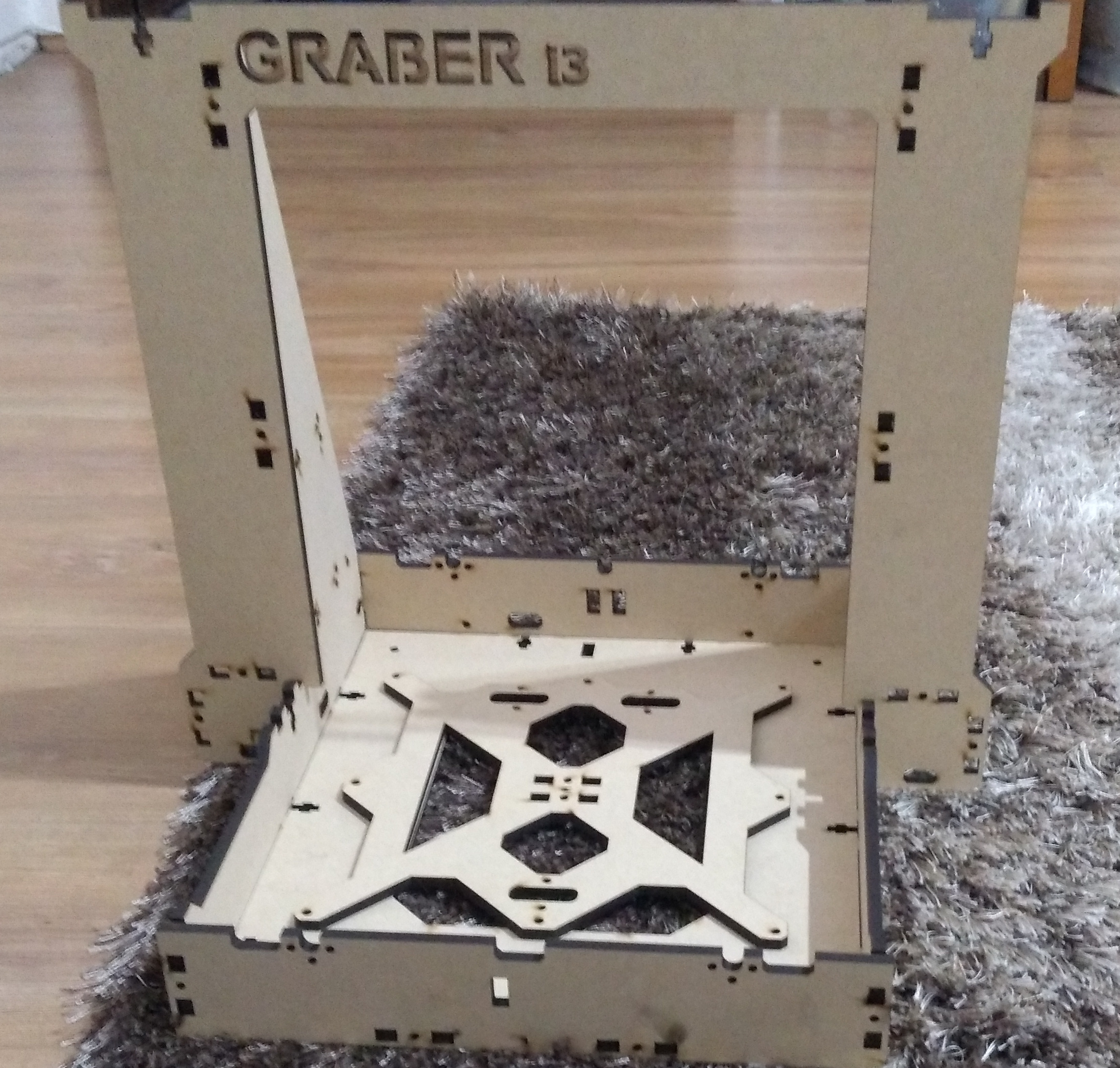
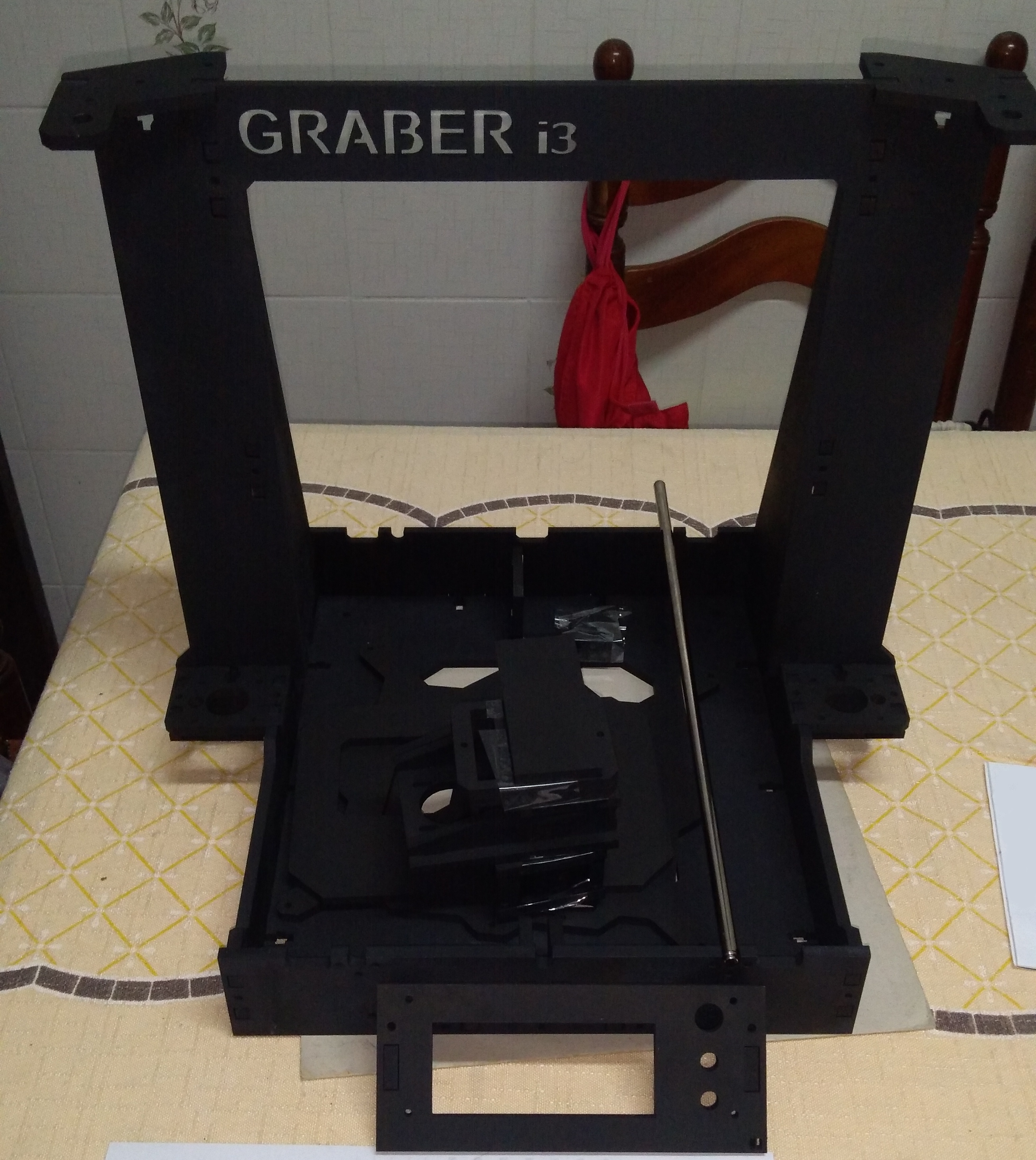
The structure of this 3D printer is a laser-cutted MDF. It is a Graber i3, based on Prusa i3, however, it uses laser-cutted parts instead of printed ones.
To do this, I bought a 90cm x 1m MDF board, cutted into two halves that could fit in a laser cutter. The resulting parts were painted using automotive spray, in order to make them more waterproof.
That structure, however, is not compatible with the display that I’m using. Then I laser cutted another frame for that display, available here.
Each axis has a pair of 8mm steel bars. Here in Brazil, some parts of 3D printers are overpriced, so I didn’t bought the ones tagged as “3D linear rods”. I took some of them from junk ink-jet printers, and the rest I bought at local stores as “8mm steel bars”.
Electronics
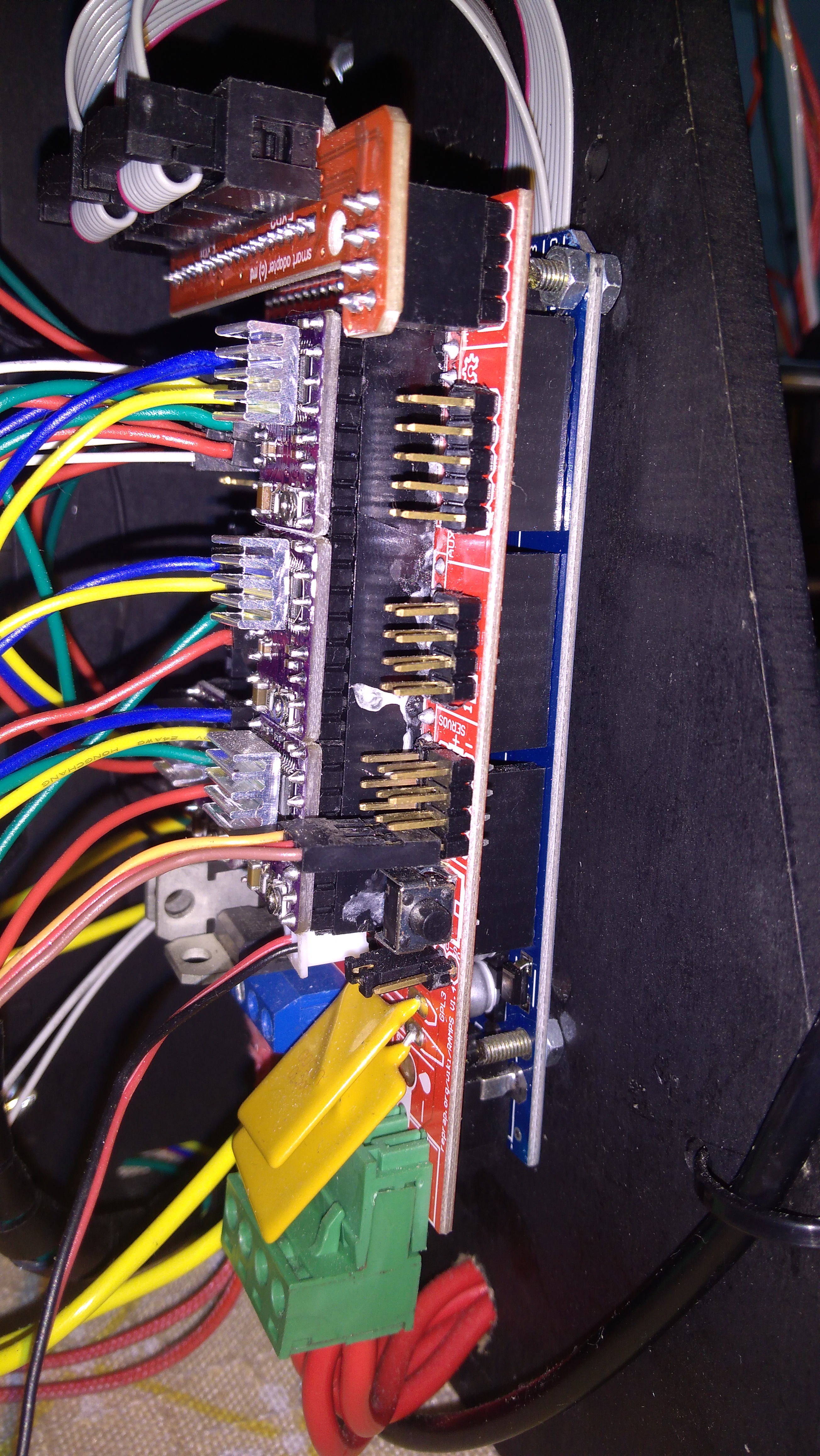
In the heart of the 3D printer there’s an Arduino Mega and a RAMPS shield. The RAMPS shield is used to control the electric components of a 3D printer.
Four DRV8825 drivers where plugged on the RAMPS. They are responsible for controlling the stepper motors. Each driver controls one of the three axes of the 3D printer, plus a fourth one for controlling the filament flow through the extruder. The RAMPS shield also allows another stepper motor for a second extruder, however, I didn’t use it as would only have one extruder (at least by now).
A RepRap Full Graphics Display is also connected to the RAMPS shield, with a rotary encoder that allows the user to control the interface and a SD card slot. Unlinke another simpler displays, this one is capable of drawing figures and it has a prettier interface than the ones the only show plain text. This display also allows to play some games 😉.
Stepper Motors
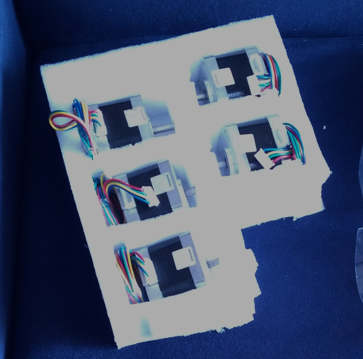
Five NEMA 17 were used. One for the X axis, one for the Y axis, two for Z axis and one for the extruder. Those steppers should be plugged on the RAMPS shield by the side of the corresponding drivers. The Z axis steppers share the same driver.
When installing the stepper motors, we need to fine tune each driver in order to provide the correct current. That tune needs to be done using a multimeter, turning the potenciometer on the top of the driver. To do this, we need to read the datasheet of the driver and of the stepper and check what should the tension between the metal screw of the potentiometer and the driver GND. Then we need to turn that screw with maximum care to not let the probe escape and short-circuit something, until it reaches the correct tension. If you short-circuit something, you can brick your Arduino (yeah, that happened to me).
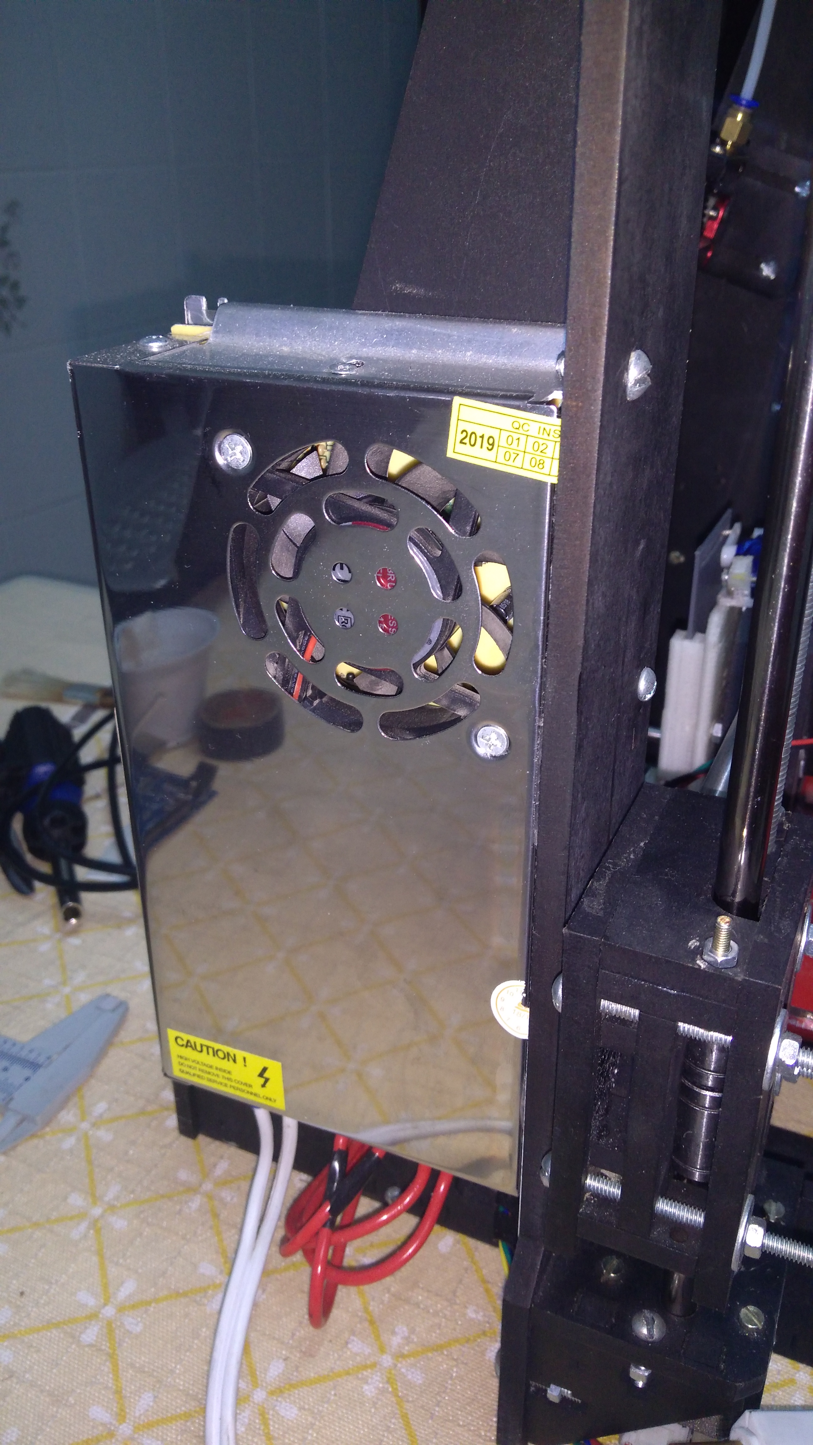
Power supply
A switching power supply provides a 12V output to the RAMPS shield. Then the shield supplies power for the Arduino and other components. The Arduino itself can be powered through USB (5V), and that’s enough for powering the display and the servo (I’ll talk about it later), however, it is not capable of moving the stepper motors, heating the bed and heating the extruder.
Heating
During the printing, one of the steppers pushes the filament towards the nozzle. Then the hot nozzle melts the filament and makes it exit through its hole. The heating element and a thermistor are coupled to the heating block where the nozzle is inserted. Above them, there’s a heatsink and a cooler. Those parts allow to control the temperature, that needs to be inside the recomended range for the chosen material.
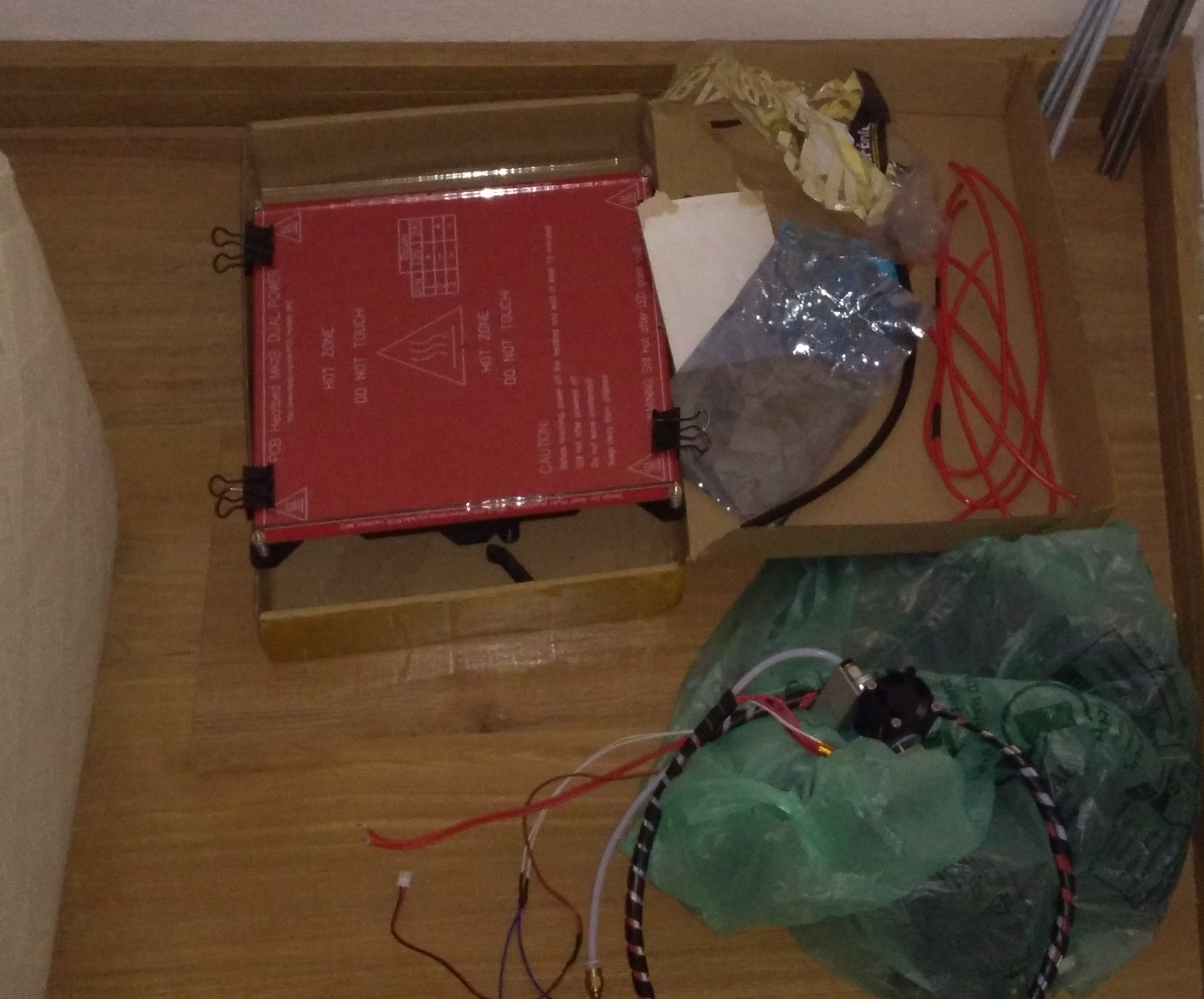
The heating bed allows better grip and better printer quality. Below it, a thermistor is placed. The heating bed acts a big resistor, which is powered with 12V by the RAMPS. It is fixed over its base using four springs, each one with a screw for leveling.
We cannot print directly over the heating bed: we need to use a piece of glass over it as a base for printing. We can use a standard 3mm glass, in a shape that fits over the heating bed without touching the screws.
Mechanical parts
The bed moves over the Y axis, the X axis moves over the Z axis, the extruder moves over the X axis. The movement of those axes is guided by linear bearings (LM8UU).
The moviment of the steppers of the X and Y axes is transmitted through a set of a belt, a pulley and a bearing for each one of them. The belts should not be too loose or too fasten.
The Z axis is moved by washers that go up and down according to the movement of the threaded bars. Each of the two threaded bars is fixed on a stepper motor using a flexible coupling.
Just like the rods mentioned before, here in Brazil compatible threaded bars could be easily found at local screw or construction stores, and they are far cheaper than the ones designed exclusively for 3D printers.
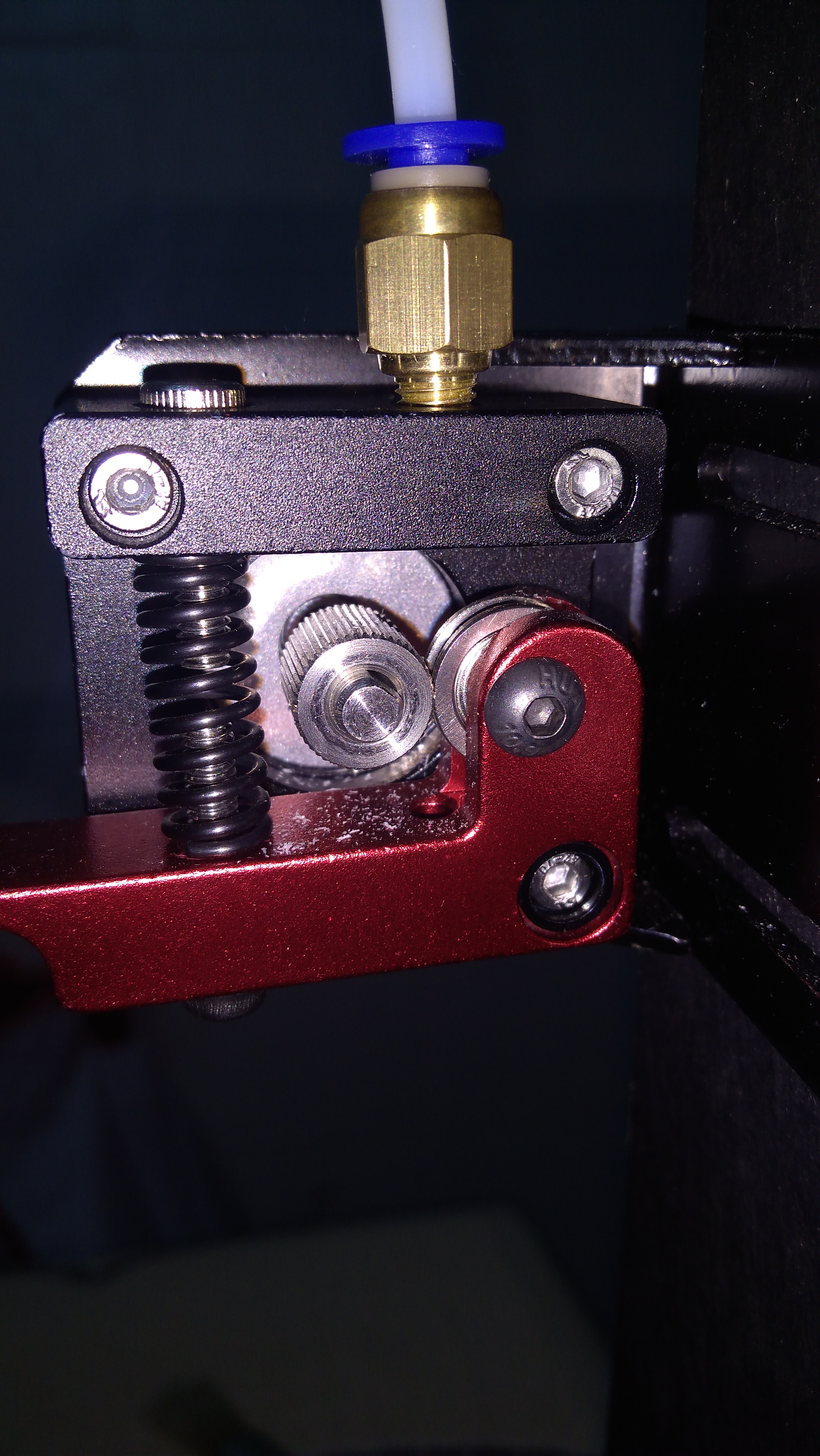
The filament movement system is composed by a lever with a spring and a bearing, that, together, push the filament against a pulley coupled to the extruder stepper. Then, the movement of the stepper motor pushes the filament through the bowden.
Endstops
In a 3D printer, the endstops are responsible to detect if the end of an axis was reached.
Due to the shape of the power supply that I’ve bought, this printer has its X axis mirrored compared to the other Graber i3s. This way, it would be cleaner to assembly it mounting the X endstop at the end of the X axis, while the Y and Z endstops are mounting at the beginning of their axes.
The endstops were mounted in the following way:
- X endstop: mounted at the right, on the MDF structure that holds the X stepper;
- Y endstop: under the heatbed, touching the back of the printer when Y = 0;
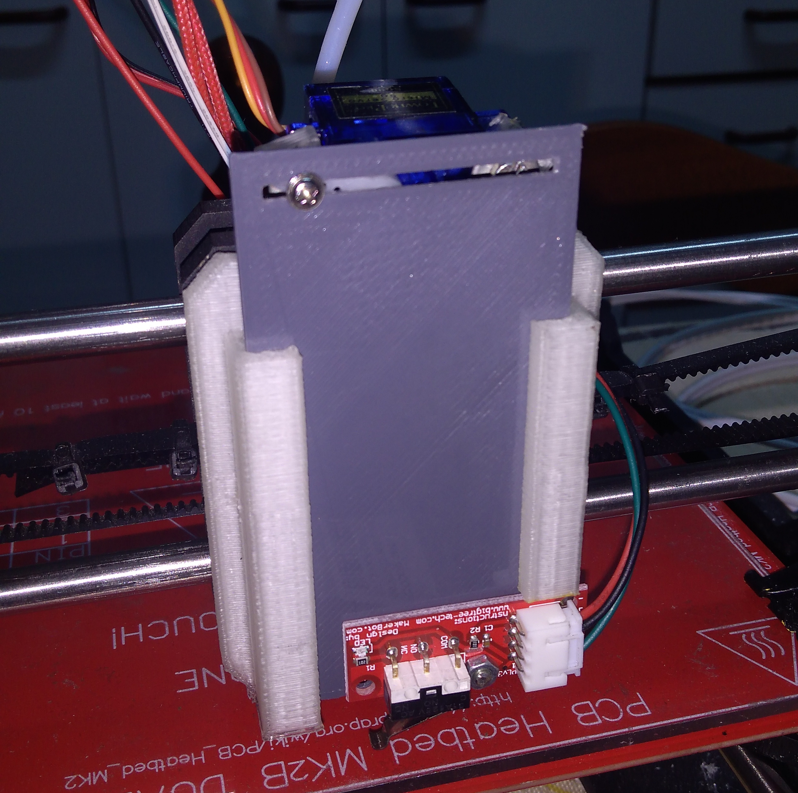
- Z endstop: mounted on a 3D printed piece, that is retracted or deployed by a servo, allowing it to be in a safe position during the print.
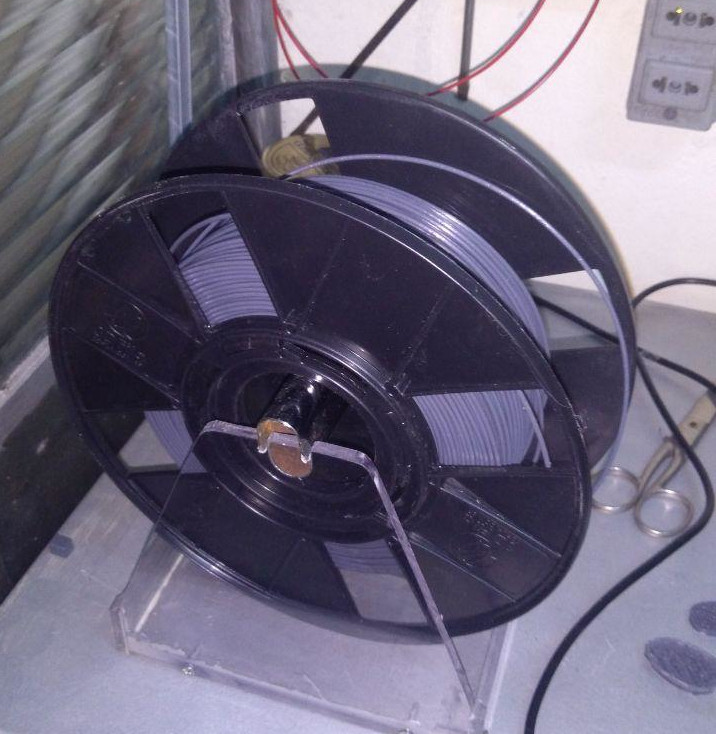
Filament support
Graber i3 doesn’t have a filament support, unlike some other 3D printers. My father made this one with some acrylic leftovers that we had at home:
Firmware
This printer uses Marlin as its firmware. Marlin is easy to be configured only using constants in two C++ header files (.h), and it has a great documentation.
So far, I needed to configure this:
- Baudrate: de 250000 para 115200
- Filament diameter: de 3mm para 1.75mm
- Enable the heatbed thermistor
- Invert endstop logic
- Set the X axis to the max position
- Steps per mm for each one of the axes
- Printing space size
- PID tuning
- Servo positions
- Interface in Portuguese
- Allow the buzzer to play different tones
- Enable SD card
- Set Full Graphics Display
- Enable the game Brickout
I maintain my own fork of Marlin here, with those configurations and other small changes.
Results
After finished, this is how the printer looks:
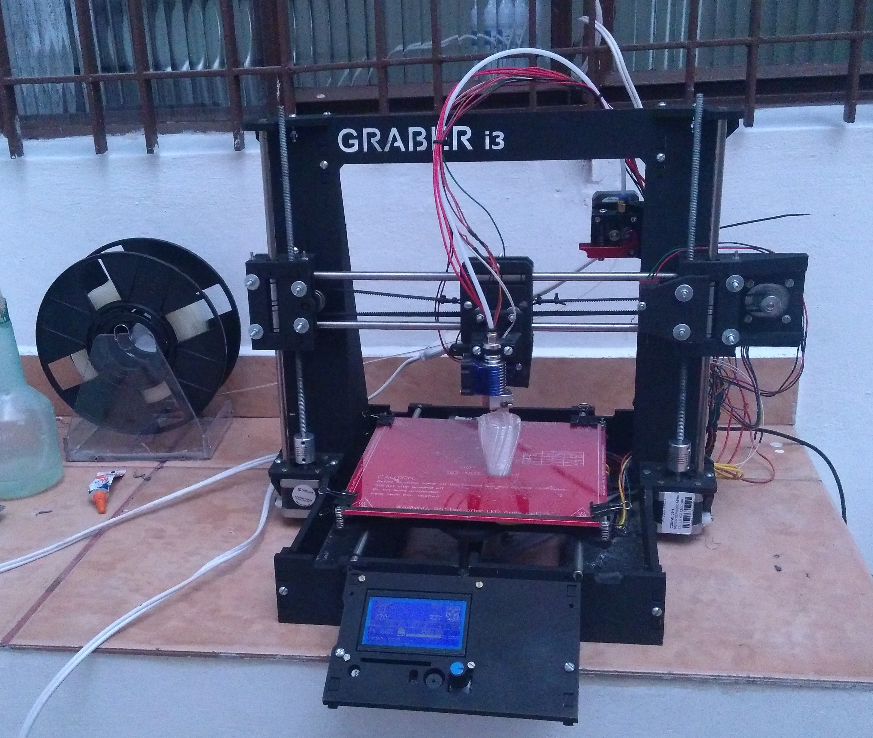
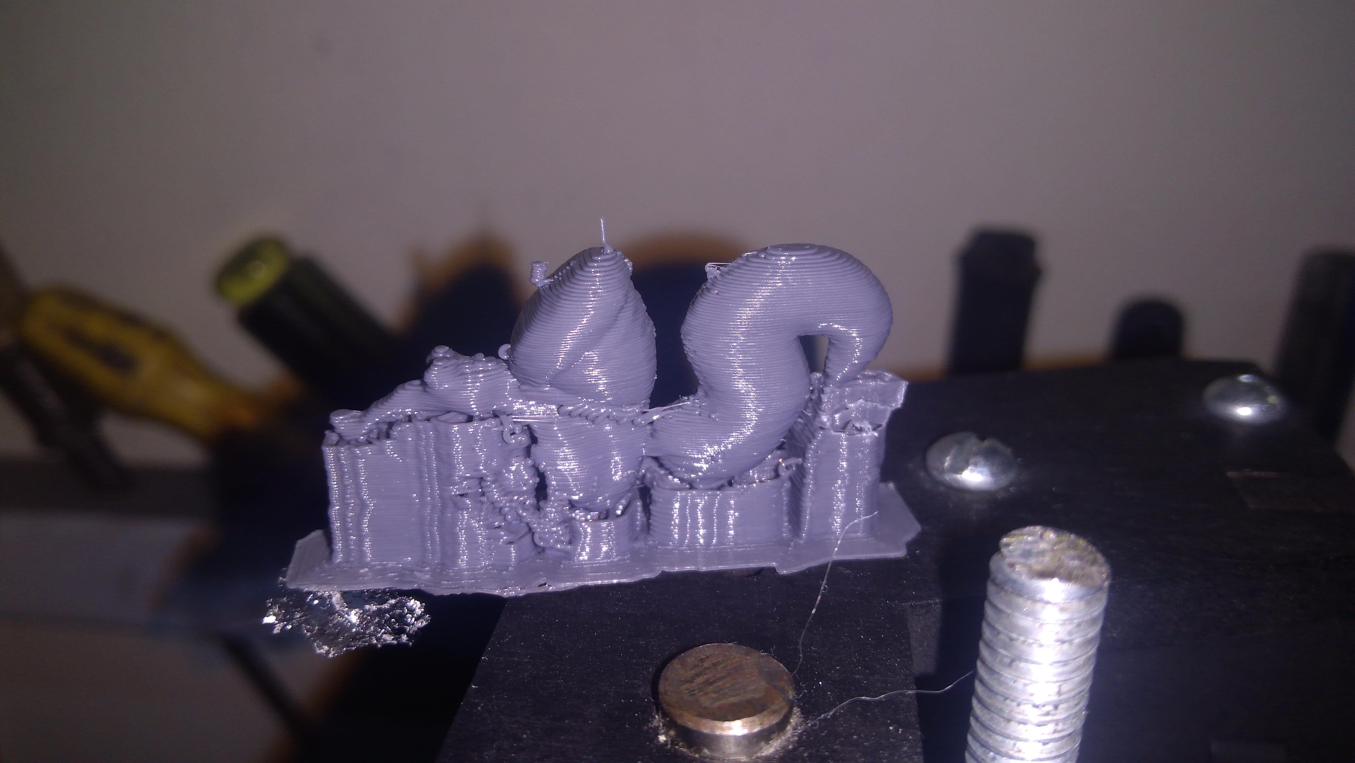
These are the first objects that I printed on it:

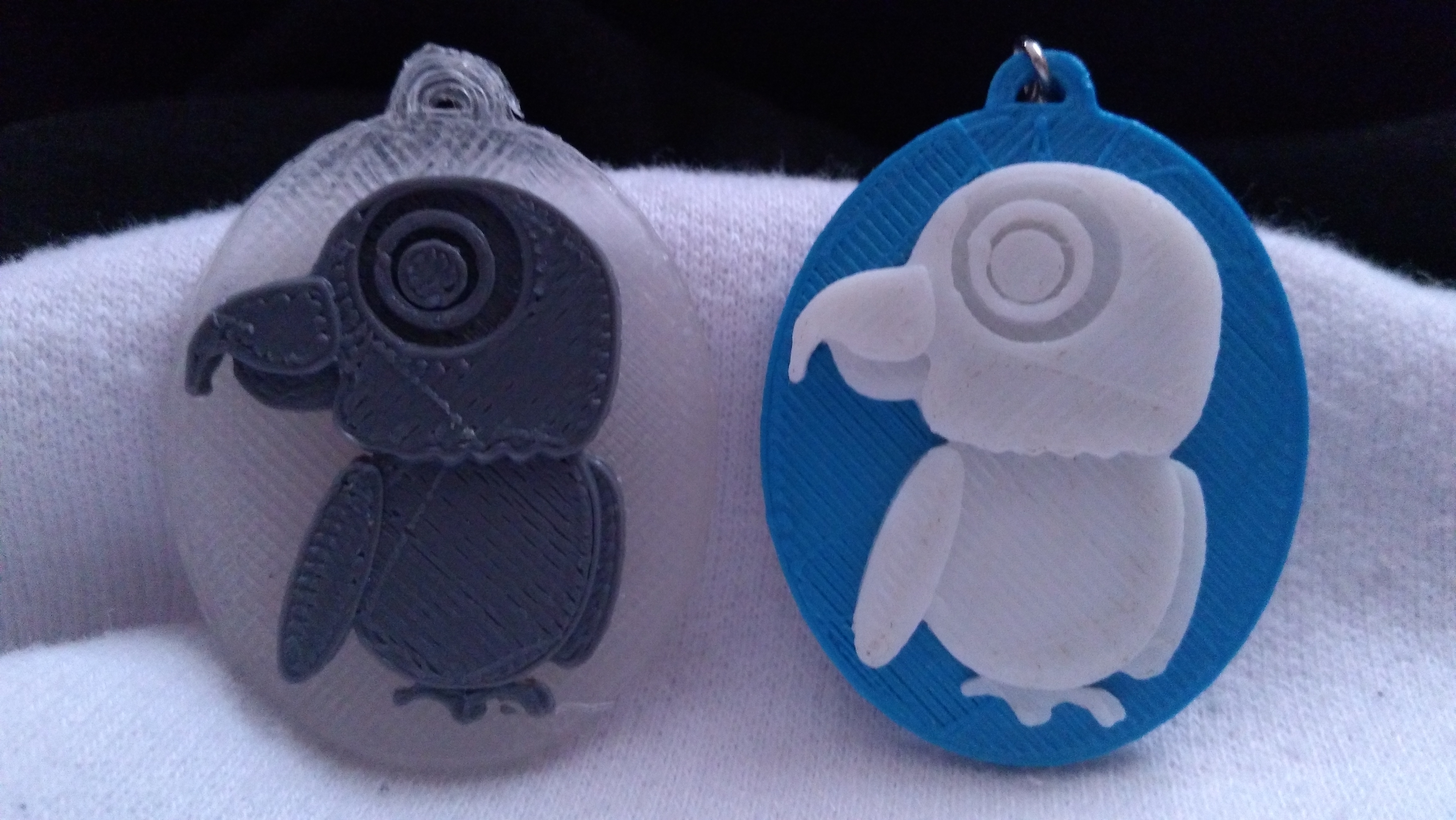
And finally, something that I wanted to print since the beginning: the Mr. FLUSP keychain. In 2019, a friend of mine printed on our university these keychains, and the result was very cool. I have one of them, and the CuraEngine configuration used to print them is available here. So, I printed another one with the same configuration, then I could compare the printing quality of my printer with the ones of my university. The result can be seen in the following picture. The blue and white is the one printed on my university, and the transparent and grey is the one printed on my 3D printer. Nothing bad for a printer that costs 70% less.
Update (2023)
Almost three years went by and this printer worked hard since then. Some improvements were made:
- A new mount for the Z endstop;
- WiFi;
- An external MOSFET for controlling the heatbed temperature, in order to decrease the current supplied by the RAMPS shield
Furthermore, after three years of printing, I’m more familiarized with the 3D printing process as a whole. My 3D prints improved a lot: